-
E-mail
yzbrave@qq.com
-
Phone
13390665885
-
Address
Room 312, No. 98, Mount Taishan East Road, Baoying County (Baiyue Power)
Product Categories
Yangzhou Baiyue Electric Co., Ltd
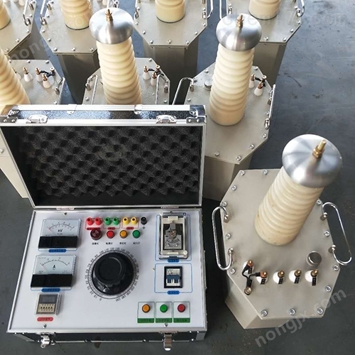


Which is a good power frequency withstand voltage test device
NegotiableUpdate on 01/17
- Model
- Nature of the Manufacturer
- Producers
- Product Category
- Place of Origin
Overview
The 100KV power frequency withstand voltage test device has the characteristics of small size, light weight, compact structure, complete functions, strong universality, and easy use. Specially suitable for conducting insulation strength tests on various high-voltage electrical equipment, electrical components, and insulation materials under power frequency or DC high voltage in power systems, industrial and mining enterprises, scientific research departments, etc. It is an important equipment in high-voltage testing.
Product Details
100KV power frequency withstand voltage test deviceIt is a new type of product produced based on the "Test Transformer" standard of the Ministry of Mechanical and Electrical Engineering, which has been greatly improved on the basis of similar products. This series of products has the characteristics of small size, light weight, compact structure, complete functions, strong universality, and easy use. Specially suitable for conducting insulation strength tests on various high-voltage electrical equipment, electrical components, and insulation materials under power frequency or DC high voltage in power systems, industrial and mining enterprises, scientific research departments, etc. It is an important equipment in high-voltage testing.
Adopting a single frame core structure. The primary winding is wound around the iron core, with the high-voltage winding outside. This coaxial arrangement reduces leakage flux and thus increases coupling between windings. The outer shell of the product is made into an octagonal structure that matches well with the core, giving the overall appearance a beautiful and elegant look.
1100KV power frequency withstand voltage test deviceModel:
Model number |
capacity |
High voltage (KV) |
High voltage current (mA) |
low voltage input |
transformation ratio |
Temperature rise ℃ |
|||
(KVA) |
AC |
DC |
AC |
DC |
voltage (V) |
current (A) |
High/Instrument |
30 minute |
|
Byyb- 1.5 / 50 |
1.5 |
50 |
70 |
30 |
15 |
200 |
7.5 |
500 |
10 |
Byyb- 3 / 50 |
3 |
50 |
70 |
60 |
15 |
200 |
15 |
500 |
10 |
Byyb- 5 / 50 |
5 |
50 |
70 |
100 |
15 |
200 |
25 |
500 |
10 |
Byyb- 10 / 50 |
10 |
50 |
70 |
200 |
50 |
200 |
50 |
500 |
10 |
Byyb- 20 / 50 |
20 |
50 |
70 |
400 |
100 |
400 |
50 |
500 |
10 |
Byyb- 30 / 50 |
30 |
50 |
70 |
600 |
100 |
400 |
75 |
500 |
10 |
Byyb- 40 / 50 |
40 |
50 |
70 |
800 |
105 |
400 |
100 |
500 |
10 |
Byyb- 50 / 50 |
50 |
50 |
70 |
1000 |
100 |
400 |
125 |
500 |
10 |
Byyb- 10 / 100 |
10 |
100 |
140 |
100 |
50 |
200 |
50 |
1000 |
10 |
Byyb- 20 / 100 |
20 |
100 |
140 |
200 |
100 |
400 |
50 |
1000 |
10 |
Byyb- 30 / 100 |
30 |
100 |
140 |
300 |
100 |
400 |
75 |
1000 |
10 |
Byyb- 40 / 100 |
40 |
100 |
140 |
400 |
100 |
400 |
100 |
1000 |
10 |
Byyb- 50 / 100 |
50 |
100 |
140 |
500 |
100 |
400 |
125 |
1000 |
10 |
Byyb- 20 / 150 |
20 |
150 |
210 |
133 |
100 |
400 |
50 |
1500 |
10 |
Byyb- 30 / 150 |
30 |
150 |
210 |
200 |
100 |
400 |
75 |
1500 |
10 |
Byyb- 40 / 150 |
40 |
150 |
210 |
267 |
100 |
400 |
100 |
1500 |
10 |
Byyb- 50 / 150 |
50 |
150 |
210 |
333 |
100 |
400 |
125 |
1500 |
10 |
Byyb- 100 / 150 |
100 |
150 |
210 |
667 |
150 |
400 |
250 |
1500 |
10 |
Note: This series of products includes 200V series taps, which can be cascaded with two or three units to form high voltages of AC 100KV, 150KV, 200KV, 300KV, DC 140KV, 210KV, 280KV, and 420KV. And according to user needs, 5-15KV medium voltage taps can be extracted from the high-voltage winding for AC withstand voltage testing of high-voltage motors. And special specifications of test transformers can be customized.
2、 Attention:
1. Connect the working circuit according to the experiment you conducted. The casing of the test transformer and the casing of the operating system must be reliably grounded. The X end (high voltage tail) of the high-voltage winding used for testing the transformer and the F end of the measuring winding must be reliably grounded.
2. When conducting a cascade test, the low voltage winding of the second and third stage test transformers forms the X end, and the F end of the measuring winding and the X end (high voltage end) of the high voltage winding are both connected to the outer shell of the current stage test transformer. The shell of the second and third level test transformers must be grounded through insulation brackets.
3. Before turning on the power, the voltage regulator of the operating system must be set to zero before the power can be turned on, closed, and the boost can begin.
4. Starting from zero, rotate the regulator handwheel at a constant speed to increase the pressure. The boosting methods include: fast boosting method, which is the 20s step-by-step boosting method; Slow boost method, i.e. 60s step-by-step boost method; The extremely slow boost method is available for selection. Starting from zero, the voltage is raised to 75% of the rated test voltage at a certain rate and speed, and then raised to the required test voltage at a rate of 2% of the rated test voltage per second, while closely monitoring the condition of the measuring instrument and the test object. If any abnormality is found in the indication of the measuring instrument or the condition of the test object during the boosting process or the testing process, the voltage should be immediately reduced, the power should be cut off, and the situation should be investigated.
5. After the experiment is completed, the voltage regulator should be returned to zero at a constant speed within a few seconds, and then the power should be cut off.
6. This product shall not be used beyond its rated parameters. Unless necessary for testing, never apply voltage or cut off power.
7. When using this product for high-voltage testing, in addition to being familiar with this manual, it is also necessary to strictly follow relevant national standards and operating procedures. Refer to GB311.1-97 "Insulation Coordination and High Voltage Test Techniques for High Voltage Transmission and Transformation Equipment"; Preventive Testing Regulations for Electrical Equipment, etc.
Similar Product Recommend