-
E-mail
530275034@qq.com
-
Phone
15618387066,17621667655
-
Address
Jincheng Road, Jing'an District, Shanghai
Product Categories
Shanghai Shenrui Testing Equipment Manufacturing Co., Ltd

Quotation for Geotextile Penetrometer
NegotiableUpdate on 01/18
- Model
- Nature of the Manufacturer
- Producers
- Product Category
- Place of Origin
Overview
The geotextile permeability tester is a testing device designed and developed using the JIGAOTEST system to detect the vertical water flow permeability of geosynthetic materials and related composite materials. 【 Scope of Application 】: Developed independently by Jigao for testing the vertical permeability performance of geotextiles and composite materials.
Product Details
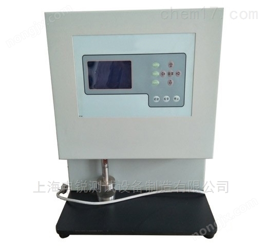
YT020YT020 geotextile permeameter(Vertical permeameter)
Geotextile permeameter is a testing device designed and developed using the JIGAOTEST system to detect the vertical water flow permeability of geosynthetic materials and related composite materials. 【 Scope of Application 】: Developed independently by Jigao for testing the vertical permeability performance of geotextiles and composite materials. 【 Related standards 】: GB/T15789, JTGE50, SL/T235, ISO11058, ASTMD4716
【 Scope of Application 】: Used for testing the vertical permeability of geotextiles and composite materials.
【 Related standards 】: GB/T15789, JTGE50, SL/T235, ISO11058, ASTMD4716
:
1. Maximum head pressure difference: 250mmH2O
2. Inner diameter of gripper: 50 ± 0.5mm
3. Applicable sample thickness: 20mm
4. Time controller: 0-99.9 seconds can be set arbitrarily, with a time control accuracy of 0.1 seconds
5. Measuring cylinder: 1000ml (measurement accuracy 10ml)
6. Water level indicator: division value, 1mm
7. Temperature range: 0-50 ℃ (accuracy 0.1 ℃)
8. Power supply: AC220V ± 10PHz
9. Dimensions: 400 × 500 × 850 (mm)
The instrument structure consists of a machine base, container, gripper, control pipeline, control circuit, and other parts. (See Figure 1 for the outline)
1. There is a control panel in front of machine base 12, which is equipped with a [work] button 8, a time counter 9, and a power switch 10. The time counter can be used to set the time. There are 4 adjustable feet 13 installed under the machine base, which can be adjusted to keep the instrument level. The machine base is equipped with components such as solenoid valves and pipelines.
2. The gripper 21 is placed inside the inner container 6 through the positioning support pin 19. The inner and outer containers are connected as a whole, each with a water outlet connected to the pipeline. The upper clamp is connected to the organic glass water level measuring cylinder 4 as a whole, and the lower clamp is a circular hole pressure plate. The lower clamp is tightened with a tightening nut 20 to clamp the sample in the middle of the clamp. The clamp is placed on the positioning support pin 19, and the water level measuring cylinder 4 has a scale facing the panel direction for easy observation. There is also a small supporting hole on the gripper for installing thermometer 3. 3. The control pipeline inlet 18 is connected to a stable water source, and the flow control switch 5 controls the water flow conduction and flow rate. The time counter controls the action conversion of the solenoid valve to determine whether the overflow water flows out from the drainage outlet 17 or the water intake 11. After pressing the [Work] button 8, the time counter 9 starts counting. When the time counter does not reach the set value, the overflow water is discharged from the water intake 11. At this time, a container is used to collect all the water flowing out of the test port, and the collected water volume is measured using a measuring cylinder; When the time counter reaches the set value, the electromagnet will activate, and the overflowing water will be discharged through the drainage port 17. After the experiment is completed, open the water outlet switch 18 and drain the water inside the instrument.
Operating procedures for geotextile permeameter
1. Clamp the sample: Take out the clamp 21, loosen the compression nut 20, place the sample flat on the lower clamp plane, press the upper clamp, then tighten the compression nut 20, place the clamp on the positioning support pin 19, and insert the thermometer 3 into the small hole on the clamp.
2. Connect the power, turn on power switch 10, and set the collection time value on time counter 9. (The setting range of time counter 9 in this instrument is 0-99.99 seconds. According to GB/T15789-1995 standard, the set time is>10 seconds.)
3. Ensure that the water outlet 18 is in the closed state and the stable water source is connected externally to the water inlet 16. Open the flow control switch 5 and align the water outlet 2 with the water level measuring cylinder 4 to inject water into the instrument until the water level exceeds the sample plane and reaches the height of the inner container 6. At this point, the head pressure difference is zero.
4. After the water level stabilizes, continue to inject water and the water begins to overflow from the inner container. Adjust the flow control switch 5 to control the water flow rate to obtain a fixed pressure difference, that is, the water level in the water level measuring cylinder 4 is stable. At this time, the overflowing water is discharged through the drainage port 17.
5. After the water head pressure difference stabilizes for 30 seconds, press the [Work] button 8, and the time counter 9 starts counting. At the same time, the solenoid valve switches the outlet, and the overflow water flows out through the intake 11. Collect the outflow of water in a container and measure the specific value with a measuring cylinder, accurate to 10mL (the collected water volume should be>1L, if it is less than 1L, the time setting value should be increased as appropriate); After reaching the set time, the solenoid valve will operate, and the overflowing water will be discharged from the drainage port 17. 6. While performing the previous steps, read the temperature value on thermometer 3, and the water temperature should be between 10-25 ℃ (accurate to 0.1 ℃).
7. Repeat steps 6.3-6.6. A total of 5 sets of readings were obtained, with water flow velocities evenly distributed between 0mm/s and 60mm/s. During the experiment, the water flow velocity was adjusted from highest to lowest.
8. Repeat steps 6.2-6.7 and test the remaining samples under the same water pressure.
9. Turn off power switch 9 and unplug power plug 14.
10. Open drain port 18 to empty the remaining water in the instrument.
11. Process the test data according to GB/T15789-1995. Note: After the power is turned on, the solenoid valve will automatically clutch and make a sound of the magnet closing. Note: After the power is turned on, the solenoid valve will automatically clutch and make a sound of the magnet closing.
working conditions
1. The instrument should be placed on a flat and stable workbench, with a height suitable for easy operation.
2. Horizontal adjustment of the instrument: After the instrument is installed, open the inlet pipe of the instrument, fill the inner container with water, adjust the four adjustable feet until the water level at the edge of the container reaches *.
3. The water supply pressure should be stable, and the water pressure fluctuation should not be too large.
4. Environmental temperature: 10-25 ℃ 5. Power supply: Ac220V ± 10PHz with reliable grounding.